I will share with you my experience in these areas as the consultant working with many best known companies all over the world.
My first post will cover conceptual models in SysML. I have found it very odd that this kind of models are almost forgotten in majority of proposed methods for MBSE. Personally, I consider it the first model to be created in the architecture. For instance, if looking to defense architecture frameworks, such as DoDAF or NAF, it is very common to create OV-1 which is called High-Level Operational
Concept Graphic. It is exactly the model, I miss in SysML. From my experience in modeling DoDAF, OV-1 is always created first when defining operational scenario of the system. It is very helpful, usually a free form view, that is very easy to create and further to relate to some physical or logical entities in the architecture. The undoubted benefit of this view is sharing core concepts of the system context between stakeholders.
To make it more clear what am I talking about, I am going to provide a high level concept graphic for water dispenser system modeled in SysML .
To model it, first I create a System Context element in SysML and call it Water Dispenser Context. Then I create IBD (Internal Block Diagram) and call it Water Dispenser Context Graphic (Fig 1).

Fig 1. Model Repository View

Fig 2. Part properties in Water Dispenser Context Graphic
1. They do allow me to specify conceptual flowing items such as information, material, human resources, and etc.
2. They do have direction.
I create three Item Flows (Fig 3).
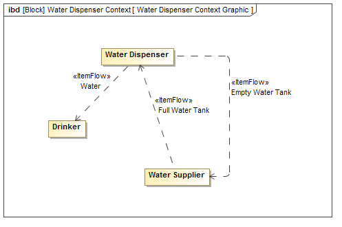
Fig 3. Item flows in Water Dispenser Context Graphic
Now we are almost done. The final step is to make diagram more sexy by adding images or even background if needed (Fig 4).

Fig 4. Water Dispenser Context Graphic
As this kind of diagram is the starting point for system architecture, elements displayed in it needs to be further detailed in functional or/and physical architectures of the system. In my future blogs I will definitely cover traceability between Conceptual, Functional, and Physical architectures and many other related topics.
Enjoy models and modeling!